Ceyhun Kirimli has a PhD. in Biomedical Engineering with areas of competence in Molecular Biology, Genetics & Biomedical Engineering and Computational Sciences with focus on Development and Design of Biosensors.

http://www.linkedin.com/in/ceyhunkirimli
http://ceyhunkirimli.com

Ad Unit

Thursday, December 26, 2013

How to control a SUPER4 USB RELAY Module?

What the heck is a Super4 USB relay module?


It is a very easy to use USB relay module with 4 relays which can be controlled via a computer (PC, Mac etc.)

Why would anyone need it?
You may have electronic devices which need to be turned on or off using a computer. Use of a computer makes it easily programmable so that you can turn on and off different devices (simultaneously or asynchronously) with precise timing.

Ingredients:


How to?

First of all you need to make sure all the drivers and software in the link above is installed in your PC. You can control it using Matlab. One way of doing this is calling the relayset.exe which would work in dos environment (you can run dos commands in command prompt).

Download and unzip the Relayset 3.0 Released 29-01-2008 in a folder. Type "cmd" in the search box which appears when you click on the windows start button (left on the taskbar) and hit enter. This would run the cmd.exe and will open the command prompt. Navigate into the folder you installed the exe by entering "cd %folder name%" (%folder name% = name of the folder you want to navigate into...) one by one, until you reach the final folder. Type "relayset " and hit enter to see a list of commands to control the super4 relay as you can see in the picture below;


As you can see it is really easy to control the board. For the setup i used during my PhD. in Drexel University in Drs. Wei-Heng and Wan Shih's lab i only used the turn on and off commands. 
All you need to do is navigate into the folder which has the relayset.exe in command prompt and turn on any relay or set of relays on a board by entering; -u(boardname)(condition of relays in binary turned in to decimal)

so if you want to turn on all relays; 
represent this in binary as : 1111 which equals to 15 in decimal;
so you need to type -s(boardname),15

or if you want to turn on relays 2 and 4 and turn off relays 1 and 3;
represent this in binary as; 0101 which equals to 5 in decimal.
so you need to type -s(boardname),5

You can turn off every relay by typing -u(boardname),15 or by setting all of them in open circuit by typing -s(boardname),0

In order to change the name of the board you need to install the Relay Mapper . A screenshot of the software is shown below;


In this case 4 boards (so totally 4x4=16 relays are controlled) are controlled; which are named "board1", "board2", "board3" and "upumpcontroller" (i am guessing this was controlling a pump..) . You can change the name of any board in this program by double clicking the board name. And do not forget to turn on the relays by checking the box on the top right. 

So, luckily Matlab has a built-in function called "system", which calls dos commands from matlab, so you can write your own function to control the relay using Matlab. An example of a Matlab function can be seen here;

You can call this function in matlab by typing;

relay(relayID, action, relaynumber) where action is simply 1 to turn on and 0 to turn off any relay, relay ID is the name given to the board you want to control and relaynumber is the decimal form of the binary set of relays you want to control;

For example if you want to turn on the relays 1 and 4 on the board named "board1" in the above picture; you can simply call;

relay(board1,1,9);

and then if you want to turn these relays off you need to call: 

relay(board1,0,9);

That is all you need. Please comment below if you have any questions....


Tuesday, November 19, 2013

Another boring info on how to remap the stock ECU of 2001 Dodge Stratus RT

Why?

To remove the top speed limiter, and increase the red line limiter to 7000 rpm instead of 6500.

Ingredients:

  • A 2001 Dodge stratus RT (same car as a 2001 Mitsubishi eclipse GT except the body) Mine is below;

  • Tactrix OpenPort 2.0 cable to download the ROM image from the stock ECU and to reflash the ECU with the modified ROM image. Mine is shown below;

Now first, you need to do some search to see if your ECU can be reflashed using the Tactrix cable. In 2001 model Dodge Stratus RT, Mitsubishi decided to put in a so called H8 Hitachi Based ECUs. However in Eclipse GTs they used the SH7 Hitachi Based ECUs. If you read the thread in Club3g above, you can download the ROM but cannot reflash an H8 ECU with a tactrix 1.3 whereas you can both download and flash SH7. That is why you need to buy a Tactrix 2.0 if you want to flash the ECU with the modified ROM.

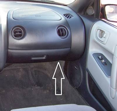
So, to make sure what ECU i had i took out the ECU which is under the glow bow (left).


Another picture from beneath the glow box;


When you open the box of the ECU you get the following:

SIDE A
SIDE B
The main CPU is in the middle in the white circle above, and the number on it is;
Yeap, it is an H8 because it says "MH8305F" on it.

When you download the latest version of EcuFlash (Version 1.44.3721) you will have a folder named rommetadata in the installation folder which includes around 600 definition files or ROM metadata models as EcuFlash calls it in the Task Info Screen;

Now what you need to have in order read the ROM in your car's ECU is a definition file that would guide EcuFlash to the memory locations in the ROM image so that you will now what values you are changing in EcuFlash. 

Of course, you need to download the stock ROM image in your ECU using the tactrix cable. It is pretty straight forward, so i am not gonna waste time here and assume you already downloaded it to your laptop. 

If you are lucky you will find a definition file in all those 600 something definitions files in the rommetadata folder. If not, EcuFlash will warn you and give you choices of starting a definition file from scratch or inherit or copy from a definition file which is in the metadata. However if EcuFlash finds a match it will load the stock ROM and show you the tables on left pane of the program. You can find stock ROMs and definition files for different cars online, so let me give you an example;


This is a modified ROM file with ID 96590107 (2005 Mitsubishi Eclipse GT manual transmission)written on the top of the window. The stock ROM you download will have its own unique ID as the file name. If not, you can find the name on position f52 line 4 of the ROM file in H8 ECUs, which you can read using the hex editor, but we will get back to that later. For now on the left pane of the picture above, you can see two tables "High Octane Fuel Map" and "Low Octane Fuel Map" is ticked. When you select them a window for each table pops up as you see. You can change individual values in this color mapped table or write your own script to generate a richer fuel map. I personally did not touch any of these, because it is a delicate process that requires experience and knowledge of EFI mappings.

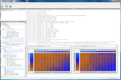
The problem you may face if you are not lucky is to use definition file for another similar car and having some of the tables in EcuFlash but they might be messed up, which happened to me as you can see in the below picture;


In the above picture i have the high octane fuel map from my stock ROM read with same definition files as stated in the Task Info of EcuFlash as;

"using metadata XML ID 85110030 from file C:/Program Files (x86)/OpenECU/EcuFlash/rommetadata/mitsubishi/eclipse/85110030.xml
which inherits XML ID 96720008 from file C:/Program Files (x86)/OpenECU/EcuFlash/rommetadata/mitsubishi/eclipse/96720008 2001 USDM Eclipse GT MT.xml
which inherits XML ID evo7base from file C:/Program Files (x86)/OpenECU/EcuFlash/rommetadata/mitsubishi/evo/evo7base.xml"

So, tables were inherited from two definition files; evo7base and 96720008 2001 USDM Eclipse GT MT. 
USDM Eclipse GT Manual Transmission is actually the exact same car as mine with a different body, so EcuFlash was on the right track but if you look at the tables above, the correct high octane fuel map should be as in the lower table but mine (upper table) had problems in the axis values. And you can see the mapping is a little bit different in these cars as well. 

To summarize what is what; 

A definition file will include the positions of the bits required for generating the tables and other values shown in above tables and etc. which are recorded in the ROM image. A ROM image is a Hex file which can be edited by a Hex editor. So if you have the definition and the stock ROM of another car similar to yours (like in my case) you can find the locations of the bits dedicated to the axis values for a table and search for a similar pattern in your car's stock ROM image and put the position values in the rather imperfect definition file you use to read your ROM.

Ok, so if you want to have the correct tables you need to change the bit locations in the definition (or ROM metadata model) file. In order to do this, you need to open the definition file used for your car by EcuFlash (in my case it was the 96720008 2001 USDM Eclipse GT MT.xml not the evo7base.xml) in notepad++. Also you need to open the definition file of the similar car (2005 Eclipse I talked about before) in Notepad++ as well. So that you can compare each definition file and find the correct position of the table axis for High octane fuel map, and find the bits in the ROM of the vehicle with the correct definition file, copy initial few of the bits and search for these bits in your cars ROM and type in the correct addresses in the definition file you are using for your car.


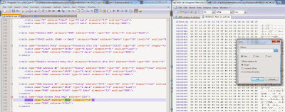
As you can see above, on line 351 of the definition of the similar car, i have the address of the bits (length of the numbers, 12 numbers in the axis for the table if you check the previous table above for Engine Load) for axis values, which is: "663a". Now you can use the go to function of the hex editor to go to that bit as seen on the right. Now copy some bits as shown below;


and paste them in the search box for your stock ROM, as shown below;


If you find more than one of the same sequence in the ROMS (you may have the same axis values written in the ROM for another table, like the High octane ignition table for example...) you should write down with what distances it occurs in the ROM of the similar car with the correct definition and use the one in your ROM appearing in the same position with respect other occurrences. But if you choose a long number of bits the occurrence should be 1.

When you find the sequence in your ROM you should locate the position of the first bit, by clicking the first "00" bit on the highlighted sequence in your ROM and the position will be written on the bottom left hand side as shown below;


Now you can change the incorrect address in your definition file to "564E", as shown below, and save it and reload the ROM for your car again in EcuFlash and see the table for the High Octane Map, voila...


Now you can generate your own definition file for your car, it would take sometime but when done, you should be able to change whatever is listed below :)
However do not change any of the mappings if you do not know what you are doing, i only changed the Rev Limit parameter from 6501 to 7000 and Speed limit from 210 to 270, which meant disabling for my car, it would never hit 270 km/h as it is :)... I bought the cable for $190 and sold it in 2 weeks for $140 and basically increased the rev limit and disabled the speed limit for $50. Please comment below if you liked it...

Monday, November 18, 2013

Why are MPG(US) and 100km/liter ratings do not match?


The question here is, why on earth for the same exact car in one country, the 100 km/litre consumption rates do not match with the MPG ratings in another country? 

Ex; BMW 328i is supposed to consume 8.1 litres/100 km in city, 5.2 litres/100 km in Highway according to the BMW's Turkish website.

Now, these numbers converts into 29 MPG(US) in city and 45 MPG(US), if you google "xxx l/100km in mpg". 

The problem is, the number in BMW's USA website is 23/35 MPG respectively for the same car. 

Another example is Nissan Juke Nismo. The Turkish website claims a consumption rating of  9.1 and 5.6 l/100km, which converts into 26/42 MPG (US). US website on the other hand claims 25/31 MPG(USA). 

For Prius C in US website the consumption is claimed to be 53/46 (city/highway) MPG(US)  whereas in Turkish website it is 3.4/3.7 l/100 km which converts to 70/64 MPG(US).

The rating for US and European cars are different so the ratio of MPG(US) to conversion from Turkish websites should be constant right? or i guessed so...?


The following chart summarizes the above, and the it will be extended in the future for more cars...Now here is a spreadsheet including the websites attached on the consumption values;

Feel free to comment below...


Boring information on how to create a communication between a HEKA PG310 potentiostat/galvanostat and a Thermo Nicolet 6700/8700 Fourier Transform Infrared Spectroscope

Ingredients:

  • Matlab
  • Heka 3xx series potentiostat/galvanostat
  • Nicolet 8700/6700 FTIR, image shown below


Why would anyone need such a communication between these devices?

Because, during spectroscopic analysis (done by FTIR) you may need to apply certain voltage patterns to your sample using the potentiostat. Of course you can do this manually as well, however an automated routine would be much faster.

How is it done?

There is an auxillary input port at the back of Nicolet 6700/8700 FTIRs. First you need to connect your remote start cable to this port and the BNC type end would go into whatever device you are using for triggering. In my case the HEKA PG310 potentiostat has DA(digital to analog) outputs in the front panel as seen below;


The four BNC type connections on the upper left hand side are DA trigger out connections which are capable of sending +5V trigger signals. The timing of the triggering can be adjusted in a Pulse Generator File created in PotMaster as described in this video in more detail. This ensures you can trigger the FTIR using PotMaster.

What is missing?

Okay, now we programmed potential patterns for each scan that is going to be run by FTIR in HEKA's Pulse Generator File (PGF). However we do not want HEKA to switch to another pattern before FTIR is ready for the next scan. So, we need to trigger HEKA between each sweep programmed in the PGF file.

So, what is next?

Next part is a little trickier, because Nicolet does not have a trigger out port (it only has an auxillary port working as a trigger-in, it can be remotely started by cannot be used to trigger another device). Thus in order to trigger the HEKA, we need the USB6501 Digital I/O device. You can install the software package come with device and write a Matlab routine to control it or just modified the one already submitted to file exchange of Matlab Central website in here. What you probably already have (to control the FTIR) is a OMNIC Macro Basic/Pro macro file which saves the background and raw spectra files in a folder every time a scan is made. In your matlab routine you can check if a new raw data is created to confirm that the FTIR scan is finished. Then you can send out a trigger signal using USB6501 to trigger HEKA for the next potential pattern.


Bumerang - Yazarkafe